Robotic Arm Research Thesis Project
Base design
The base design is working well as is the base. It will need to be changed slightly to attain different functionality such as dipping in multiple different solutions. The design allows this to be changed to perform different experiments in the future. The anti-spill has not been 100% tested but can see it having problems if spilt as it has the potential to leak onto the electronics and damage the acrylic base. This will need to be addressed in the future. The vibrations from the motors, vibrate the solutions, this may be fixed with an anti-vibration mount for the beaker.Arm design
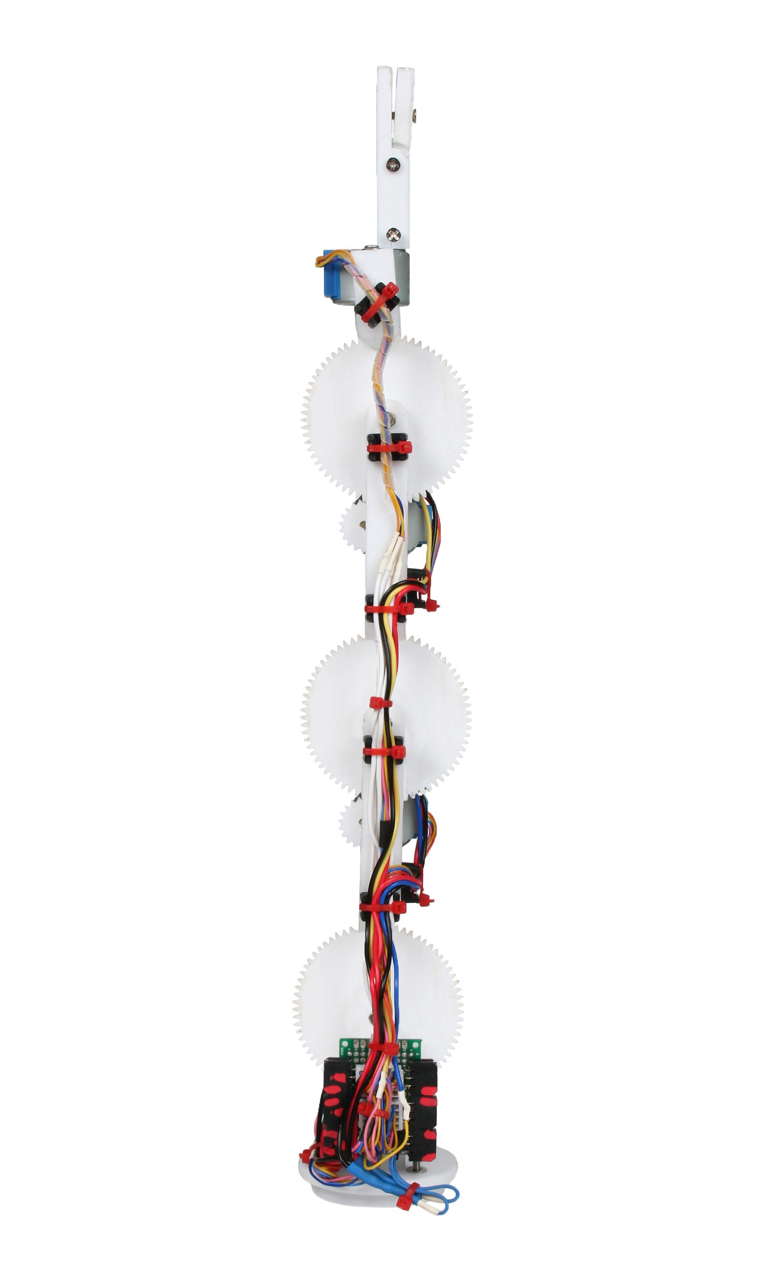
The construction of the arm took a while to start due to organising the parts sourcing from overseas. The arm is constructed from 3D printed parts and works well as a prototype. The joins are a bit lose due the space between the teeth on the gears which makes the arm jolt a somewhat resulting in a less then smooth option. This will need to the addressed on the next generation of machine. There were 3 prototypes for the arm, the first used a 5:1 gear ratio at each joint and an encoder within each gear for positioning. The sprung brush contactor for the encoders were problematic. To overcome this, the second design had the 5:1 gears negated with the steppers on a direct drive to the joint with a potentiometer. This did work but the steppers were skipping steps because it needed more torque and need the 5:1 reduction ratio. The potentiometer worked well so it was elected to mesh the two designs together to have the 5:1gear meshing and the potentiometers. This arm design proved successful and performs the best. The wires were going to be on the encoder as sliprings but since the its not getting used, the wires are going down the arm attached using cable ties and cable ties mounts.Electronics
The same with the arms, the constructions of the electronics were delayed by the ordering and shipping of the parts. The PCBs were given to me for this project to try. The PLEX board give more flexibility than other Arduino development boards. The board has a LCD, SD and up to 32 inputs and outputs that will be required for this project. PLEX uses a ATMEGA328 which is the same as the Arduino UNO uses. The arm uses stepper motor to move the joints around and requires drivers to control them. These drivers are a HR4988 which requires 2 control pins to make the stepper step in either forwards or backwards. One pin is the directional and the other is the step, a pulse to the step pin will make the motor step in a direction dependent on the directional pin. If the directional pin is HIGH the motor will spin one way and if the directional pin is LOW then the motor will spin the other way.Kinematics
The kinematics is one of the important parts of the program to get correct. The Equation 5.1 are the causations that need to be done to for the 2 main joints. c =(x^2+y^2-DistancesA^2-DistancesB^2)/(2*DistancesA*DistancesB) s = √(1-c^2 ) JointB= atan2(s,c) k1 = DistancesA+DistancesB*cos(JointB) k2 = DistancesB*sin(JointB) JointA=atan2(y,x) - atan2(k2,k1); Equation 5.1 KinematicsProgram
Since the arm now uses potentiometer instead of the encoder, it has open other pins on the board that need to be used for the SD card. This allows the SD card to be used to program the arm to preform functions for the experiment. It has also simplified the program removing the calculations for each encoder of the arm and removing the function for rest to precisely know where each joint is angled. The program for the electronics is almost finished because there are some positioning errors with the arm that need to be. The arm can work without this but it cannot travel to the correct position because of this error. The SD card hold all the programs and functions for the and is to easily program the arm to do anything that is need from the arm. The program could be programmed directly into main program on the ATMEGA328P but is not practical because then the program will need to be debugged.


