Tinkers Projects
Imagine | Develop | Create
I2C Interrupt/Encoder
Categories: Projects


I2C Interrupt/Encoder
Categories: Projects
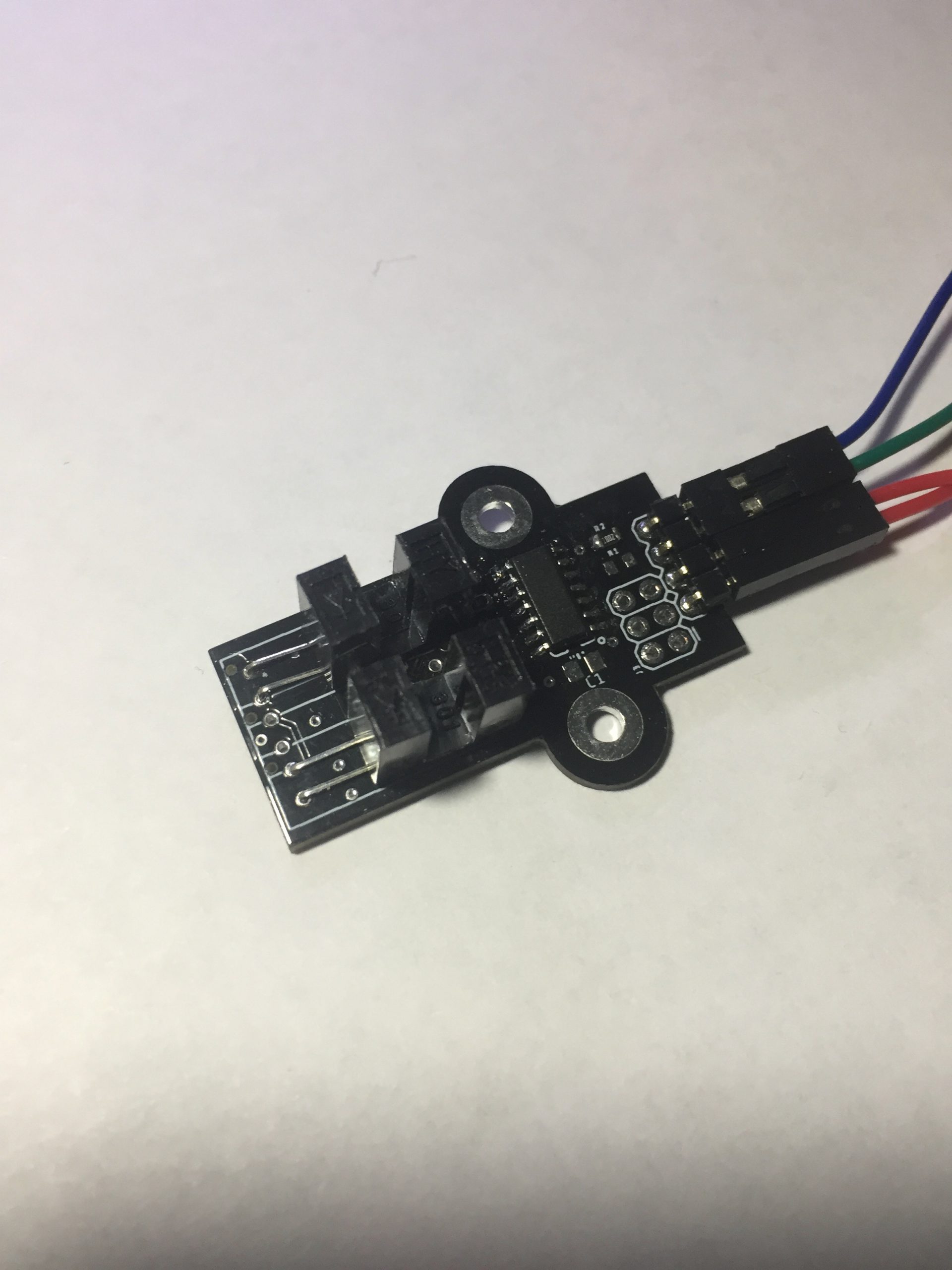
This device is an I2C interrupt or encoder which can count the rotation of a shaft. The device can determine speed, count of rotation and direction. If the direction is reversed, the count will start decreasing the count, this will give a position value of the. I made this device because it will be used on a robot driving axle to check the position of the robot. I could have got the main controller of the robot to do this but I was worried that the controller may miss interrupts. The robot would need to read 4 inputs with the rest of the program. By separating this function to an external device, it is less likely to miss interrupts and to keep count because that's all it is doing. It uses an ATTINY84 to read the input and when requested, it will send the current count var I2C. The input can be read from an external encoder or photo interrupts mounted on the PCB. There can be one or two photo interrupts mounted on the PCB. If there is only one input, the device can only count the number interrupt and speed. If there are two input, the device can count the number interrupt, direction and speed. There are through holes in the centre of the PCB for one photo interrupts or they can be placed side by side.
This device is an I2C interrupt or encoder which can count the rotation of a shaft. The device can determine speed, count of rotation and direction. If the direction is reversed, the count will start decreasing the count, this will give a position value of the. I made this device because it will be used on a robot driving axle to check the position of the robot. I could have got the main controller of the robot to do this but I was worried that the controller may miss interrupts. The robot would need to read 4 inputs with the rest of the program. By separating this function to an external device, it is less likely to miss interrupts and to keep count because that's all it is doing. It uses an ATTINY84 to read the input and when requested, it will send the current count var I2C. The input can be read from an external encoder or photo interrupts mounted on the PCB. There can be one or two photo interrupts mounted on the PCB. If there is only one input, the device can only count the number interrupt and speed. If there are two input, the device can count the number interrupt, direction and speed. There are through holes in the centre of the PCB for one photo interrupts or they can be placed side by side.


