Tinkers Projects
Imagine | Develop | Create
Flat PCB LED Controller
Categories: Lighting


Flat PCB LED Controller
Categories: Lighting
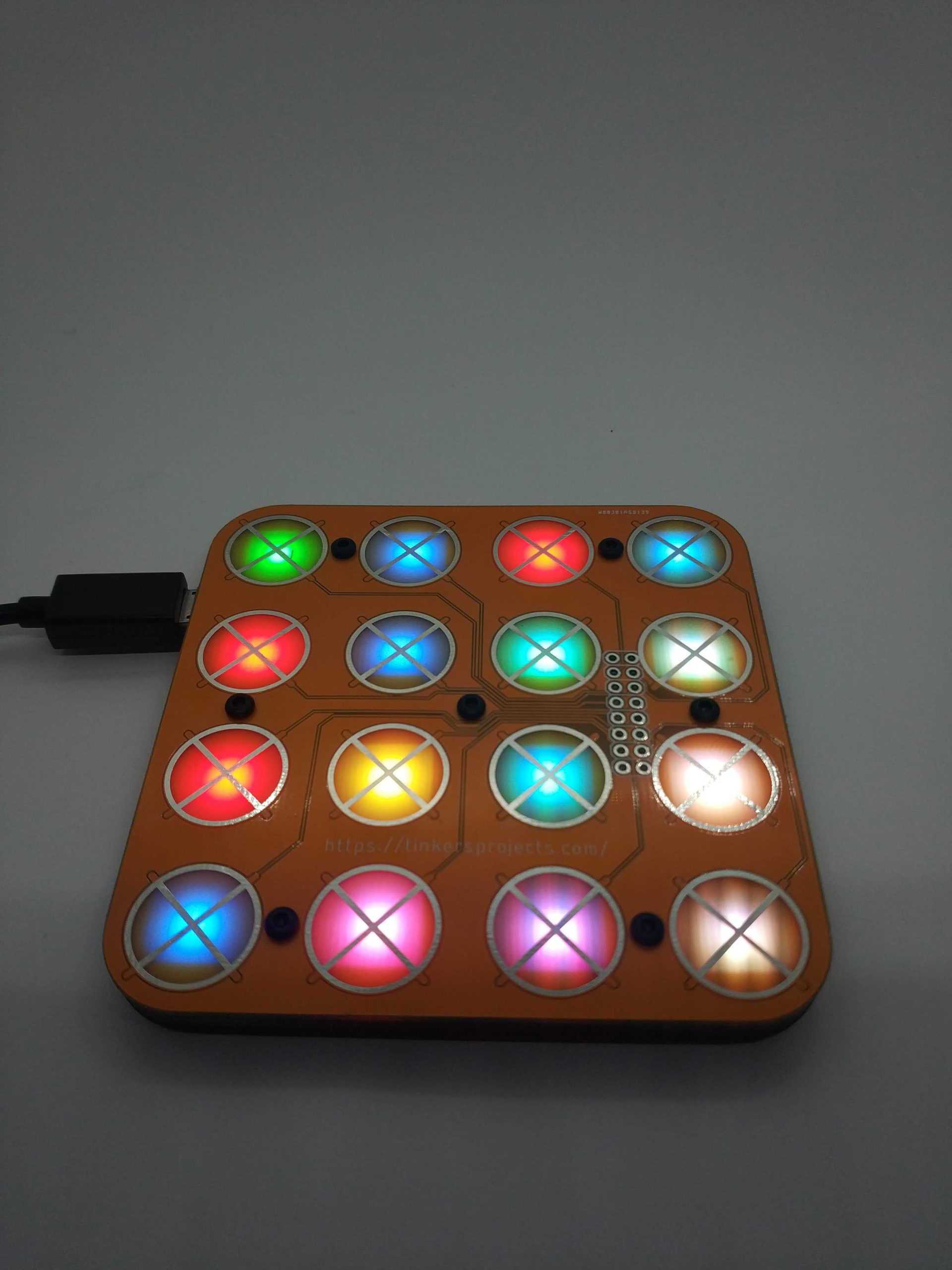
I wanted to see if I could create the thinnest controller I could. This controller is an experiment to see if I can make a flat controller which is less than 10mm. I wanted to experiment with the LED light coming through the PCB and to see capacitive touch could be used. The controller comprised of 5 PCBs, 1 top PCB, 1 bottom PCB and 3 inner PCBs. The top PCB has holes on the solder mask and copper to allow the light through and has a copper X that is used for the capacitive touch. The capacitive touch is used to allow the buttons to be pressed and interface with the controller. The bottom PCB is where the microcontroller is mounted with the USB serial interface, capacitive touch and RGB LEDs. The inner PCB allow spacing between the bottom and top layers with cut outs for components. The Processor is an ATMEGA328P at 16Mhz running the Arduino boot loader. The LEDs are WS2812B which can be individually controlled through 1 pin. This saves lots of pins on the microcontroller. The capacitive touch controller is a TTP229 and the microcontroller uses I2C/2 wire to communicate to it. The Controller needs more development put into the device before it is usable. Future development would include a different USB serial interface and output controller (maybe WiFi). The controller works and would consider using a similar interface for other projects
I wanted to see if I could create the thinnest controller I could. This controller is an experiment to see if I can make a flat controller which is less than 10mm. I wanted to experiment with the LED light coming through the PCB and to see capacitive touch could be used. The controller comprised of 5 PCBs, 1 top PCB, 1 bottom PCB and 3 inner PCBs. The top PCB has holes on the solder mask and copper to allow the light through and has a copper X that is used for the capacitive touch. The capacitive touch is used to allow the buttons to be pressed and interface with the controller. The bottom PCB is where the microcontroller is mounted with the USB serial interface, capacitive touch and RGB LEDs. The inner PCB allow spacing between the bottom and top layers with cut outs for components. The Processor is an ATMEGA328P at 16Mhz running the Arduino boot loader. The LEDs are WS2812B which can be individually controlled through 1 pin. This saves lots of pins on the microcontroller. The capacitive touch controller is a TTP229 and the microcontroller uses I2C/2 wire to communicate to it. The Controller needs more development put into the device before it is usable. Future development would include a different USB serial interface and output controller (maybe WiFi). The controller works and would consider using a similar interface for other projects