Tinkers Projects
Imagine | Develop | Create
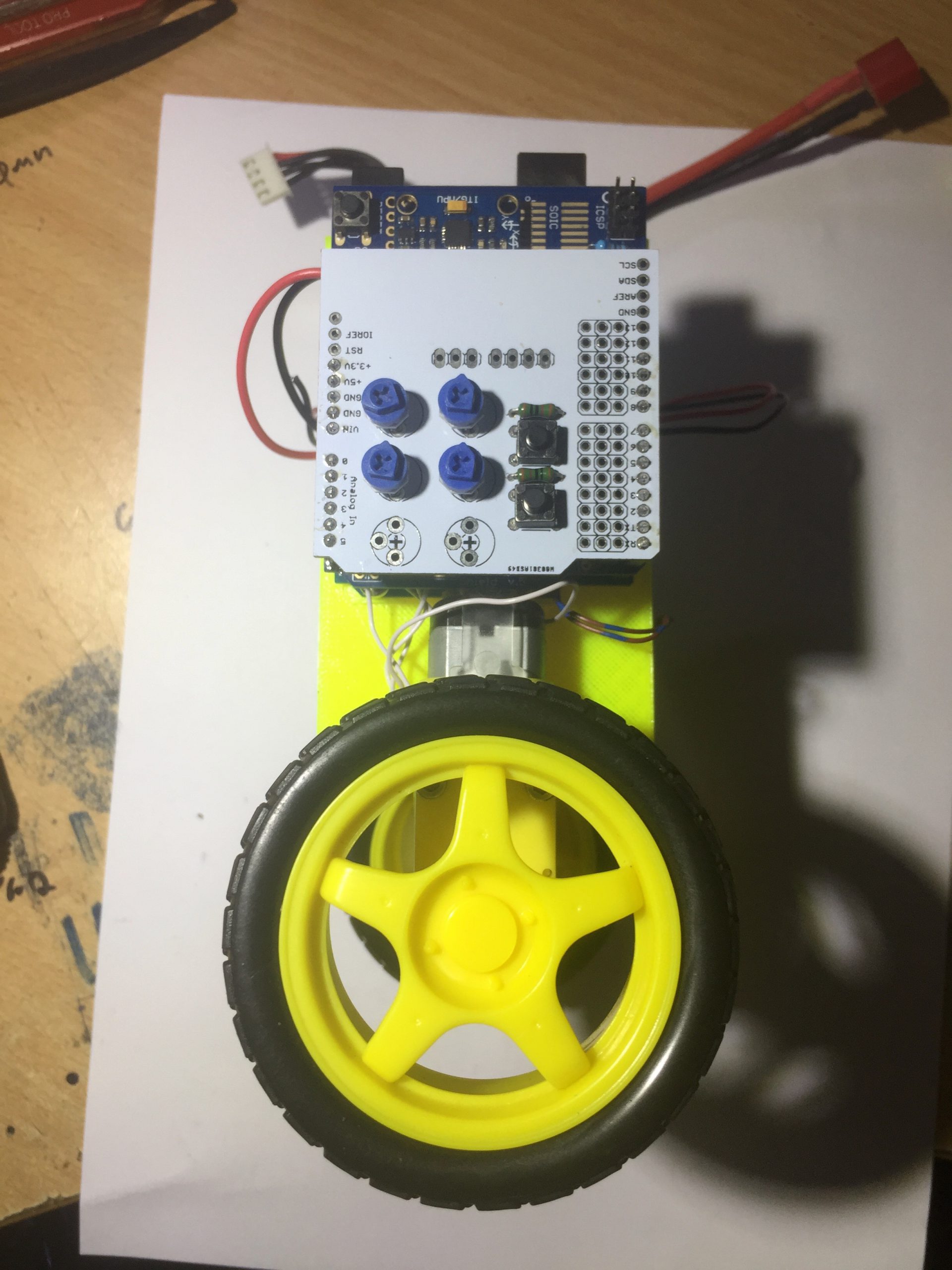

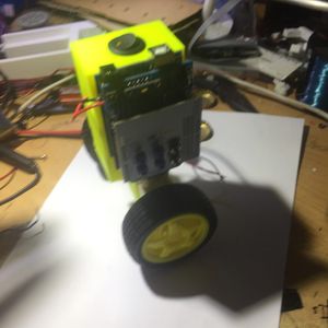


This robot represents an inverted pendulum where the robot is required to stay upright. If the robot gets pushed or a disturbance is added to the robot, the robot will try and correct it. This robot was made to help learn how a PID controller works as a feedback system, this balancing robot was made. The robots that were given to us to were large and used a potentiometer to sense the angle of the inverted pendulum. This robot uses MPU5060 to sense the angle, an Arduino UNO to process the PID controller and an L293D to drive the motors. This is a basic feedback system but the main error correction is done within the Arduino ATMEGA328P. The program uses the Arduino PID Library by Brett Beauregard found here. A potentiometer Arduino Shield (found here) was used to control the gain and parameters of the PID on the fly, making it easy to set. 2 of the potentiometers were removed from the board to ensure the I2C bus on pins A4 and A5 could work without problems. Servo and Potentiometer Arduino Shield found: https://github.com/tinkersprojects/Servo-and-Potentiometer-Arduino-Shield The PCB can be purchased from: https://tinkersprojects.com/product/servo-and-potentiometer-arduino-shield/ Arduino PID library: https://github.com/br3ttb/Arduino-PID-Library/ Get the parts at: https://www.thingiverse.com/thing:2858039
This robot represents an inverted pendulum where the robot is required to stay upright. If the robot gets pushed or a disturbance is added to the robot, the robot will try and correct it. This robot was made to help learn how a PID controller works as a feedback system, this balancing robot was made. The robots that were given to us to were large and used a potentiometer to sense the angle of the inverted pendulum. This robot uses MPU5060 to sense the angle, an Arduino UNO to process the PID controller and an L293D to drive the motors. This is a basic feedback system but the main error correction is done within the Arduino ATMEGA328P. The program uses the Arduino PID Library by Brett Beauregard found here. A potentiometer Arduino Shield (found here) was used to control the gain and parameters of the PID on the fly, making it easy to set. 2 of the potentiometers were removed from the board to ensure the I2C bus on pins A4 and A5 could work without problems. Servo and Potentiometer Arduino Shield found: https://github.com/tinkersprojects/Servo-and-Potentiometer-Arduino-Shield The PCB can be purchased from: https://tinkersprojects.com/product/servo-and-potentiometer-arduino-shield/ Arduino PID library: https://github.com/br3ttb/Arduino-PID-Library/ Get the parts at: https://www.thingiverse.com/thing:2858039